CS688 Final Project Demo
Author’s Note
This is a summary of features implemented in a raytracer for academic credit in the course CS 688 Computer Graphics at the University of Waterloo.
Texture and Bump Mapping
Comparison of a Cornell box with and without texture mapping. The back wall is textured with a Hubble image of the Helix nebula, and the red and mirror balls are normal mapped as a brick wall. The mirror ball demonstrates the normal map affects every lighting interaction. The third image demonstrates both mappings can be applied simultaneously.
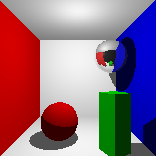
Figure 1: No Texture or Bump Mapping
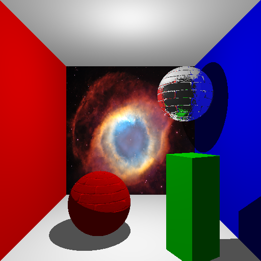
Figure 1: Texture and Bump Mapping
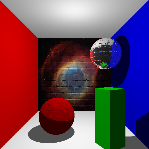
Figure 1: Texture and Bump Mapping on Same Geometry
Photon Mapping
Comparison of the raytracer with photon mapping effects. Note the colour bleed with the global illumination photon map and the concentrated refracted light under the glass and increased reflection in the ceiling with the caustic photon map. Global illumination uses 512 nearest neighbours while caustics uses 64. Image 5 shows an explicit photon map for both global illumination and caustics for the cornell box. Note the red and blue photons bleeding into the middle.
Image 6 shows the runtime for an empty Cornell box with global illumination turned on and 512 maximum sampled photons for the irradiance estimate. Notice that the KD Tree has nearly linear runtime on the semilog-x scale, whereas the non-KD Tree doubles in runtime for every doubling of photons. The KD Tree has a best-fit slope of 1.1122 on the semilog-x scale.
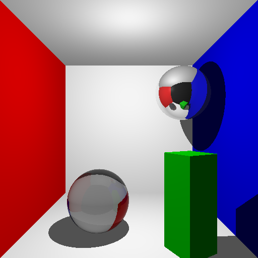
Figure 2: No Photon Map
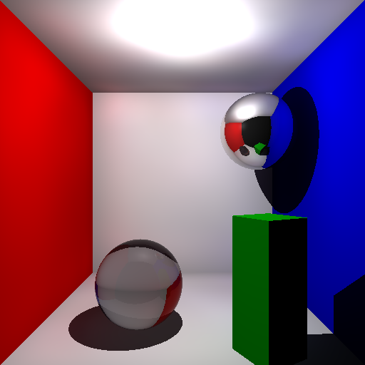
Figure 2: Global Illumination Only
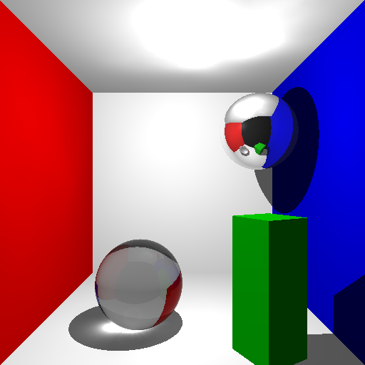
Figure 2: Caustics Only
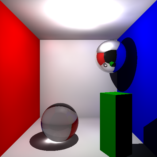
Figure 2: Global Illumination and Caustics
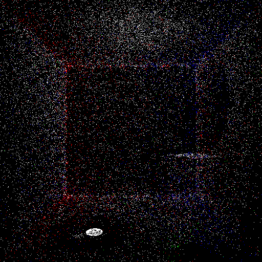
Figure 2: Photon Map
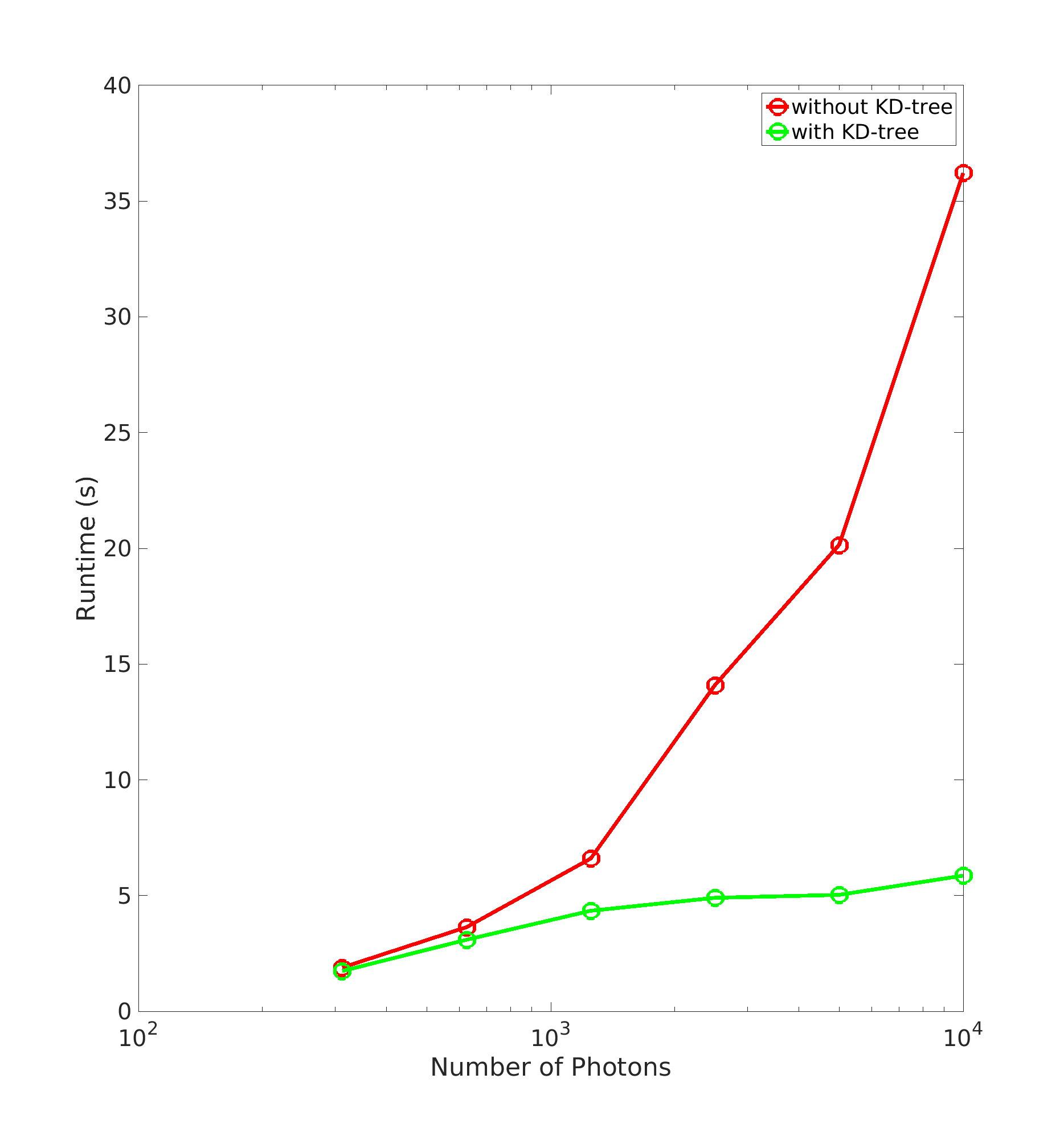
Figure 2: KD Tree Timings
Filters
Comparison of filters for a simple Cornell box with direct sampling of the global illumination map (including direct illumination), using 256 photons. Direct illumination by shadow rays is turned off to better visualize the noise in each filter. The cone filter uses k=1 and the Gaussian filter uses the parameter values provided by Jensen 2002.

Figure 3: No Filter
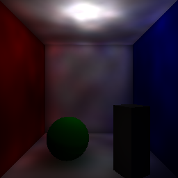
Figure 3: Cone Filter
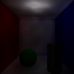
Figure 3: Gaussian Filter
Plasma
Rendering of plasmas. The floor has been recoloured grey to better show the effect. Notice the colour shift between the edges of the material and the center, where the material is thicker. Also notice that plasmas are rendered correctly even in the mirror reflection. Note that image 1 and 2 have different materials set, while 2 and 3 both have materials tagged as plasma, which are not rendered at all when the compile-time flag is unset.
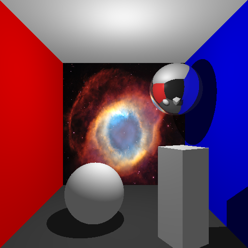
Figure 4: Basic Geometry
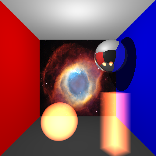
Figure 4: Plasma
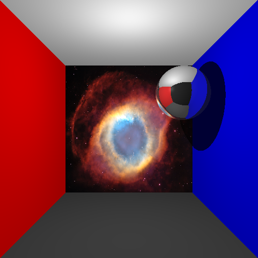
Figure 4: Plasma Rendering Off
Subsurface Scattering
Comparison of the raytracer with and without subsurface scattering. Notice the light emittance through the material in the back-lit, subsurface render, and the more transluscent reflectance in the top-lit. Note the abnormal lighting underneath the box as an artifact of our sampling method.
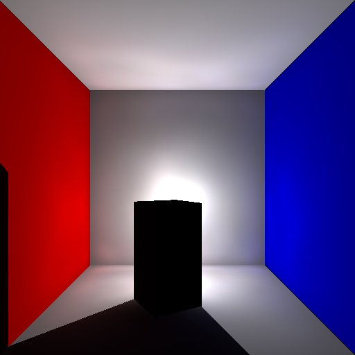
Figure 5: No Subsurface Scattering, Back Lit

Figure 5: With Subsurface Scattering, Back Lit
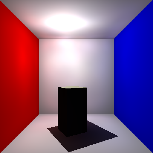
Figure 5: No Subsurface Scattering, Top Lit
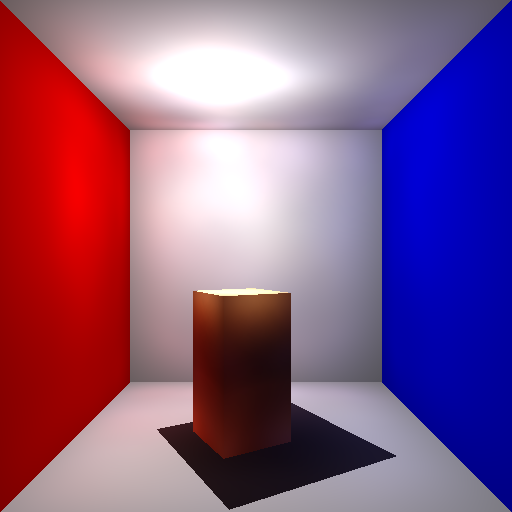
Figure 5: With Subsurface Scattering, Top Lit
Supersampling
Comparison of an image (1) without and (3) with supersampling. Supersampling used a threshold of 2.0 and 32 supersampling rays. Notice that edges are less harsh in the supersampled image, yet still respects the geometry. (2) highlights which pixels were supersampled in pure red. Notice that the edge detection operator used may miss edges that are relatively low contrast, unless the threshold is lowered.

Figure 6: No Supersampling

Figure 6: Supersampling Map
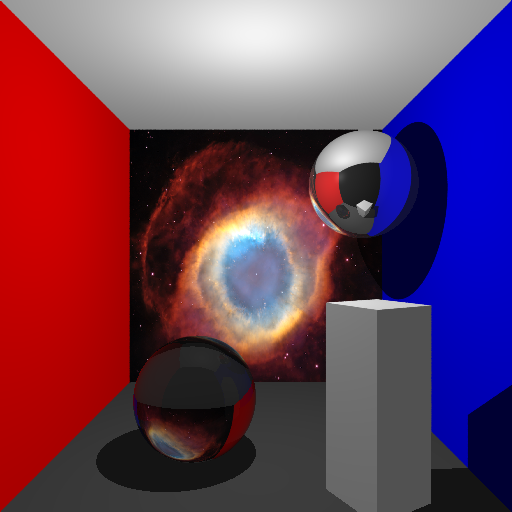
Figure 6: Adaptive Supersampling
Phong Shading
Comparison of a mesh without Phong shading, and with Phong shading applied. Notice the faceted faces become smoothed out due to the interpolation of vertex normals.
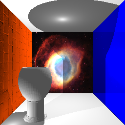
Figure 7: No Phong Shading
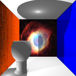
Figure 7: With Phong Shading
Final Image
Comparison of our raytraced image with Claesz’ original painting.
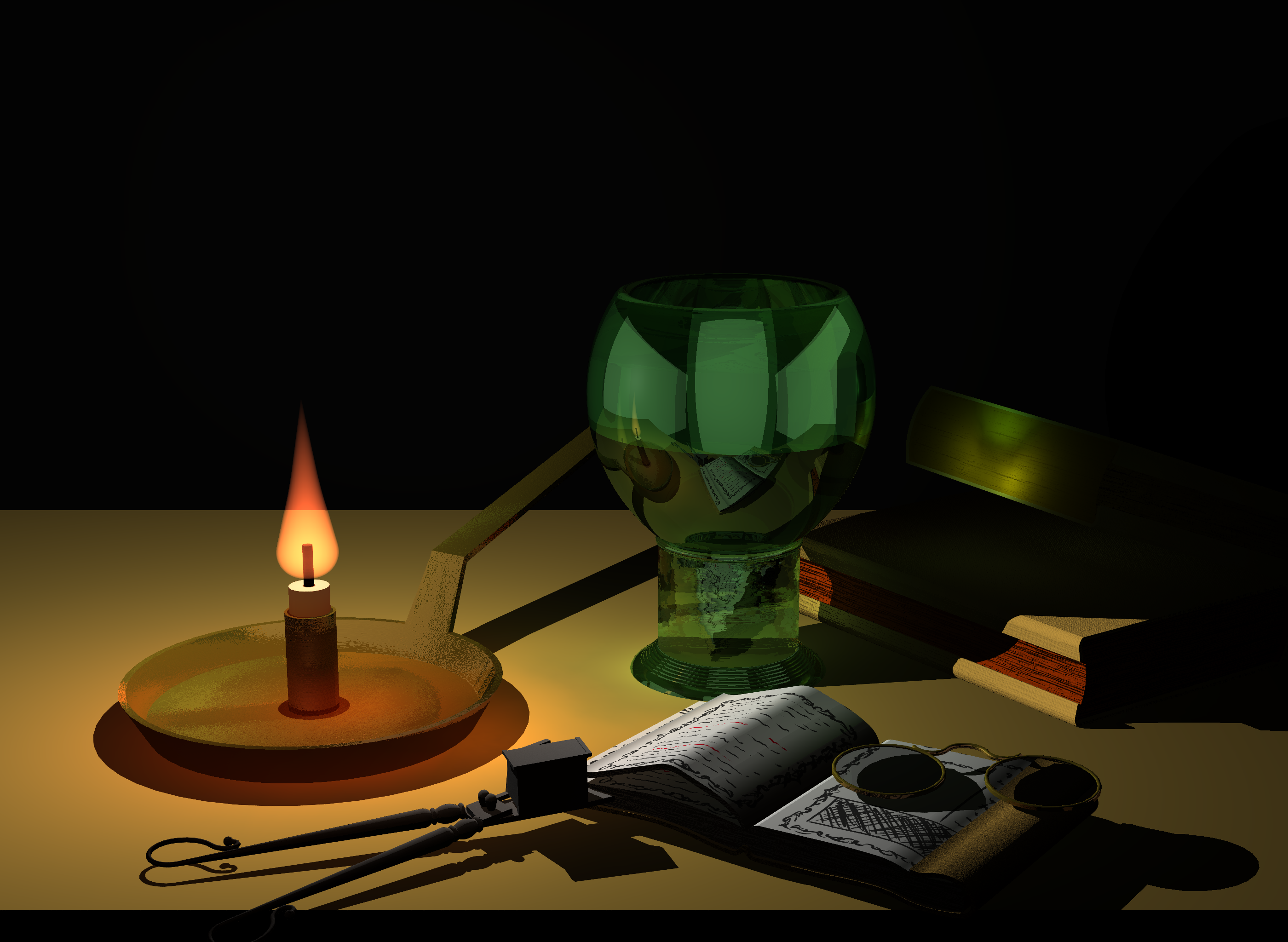
Figure 8: Final Render
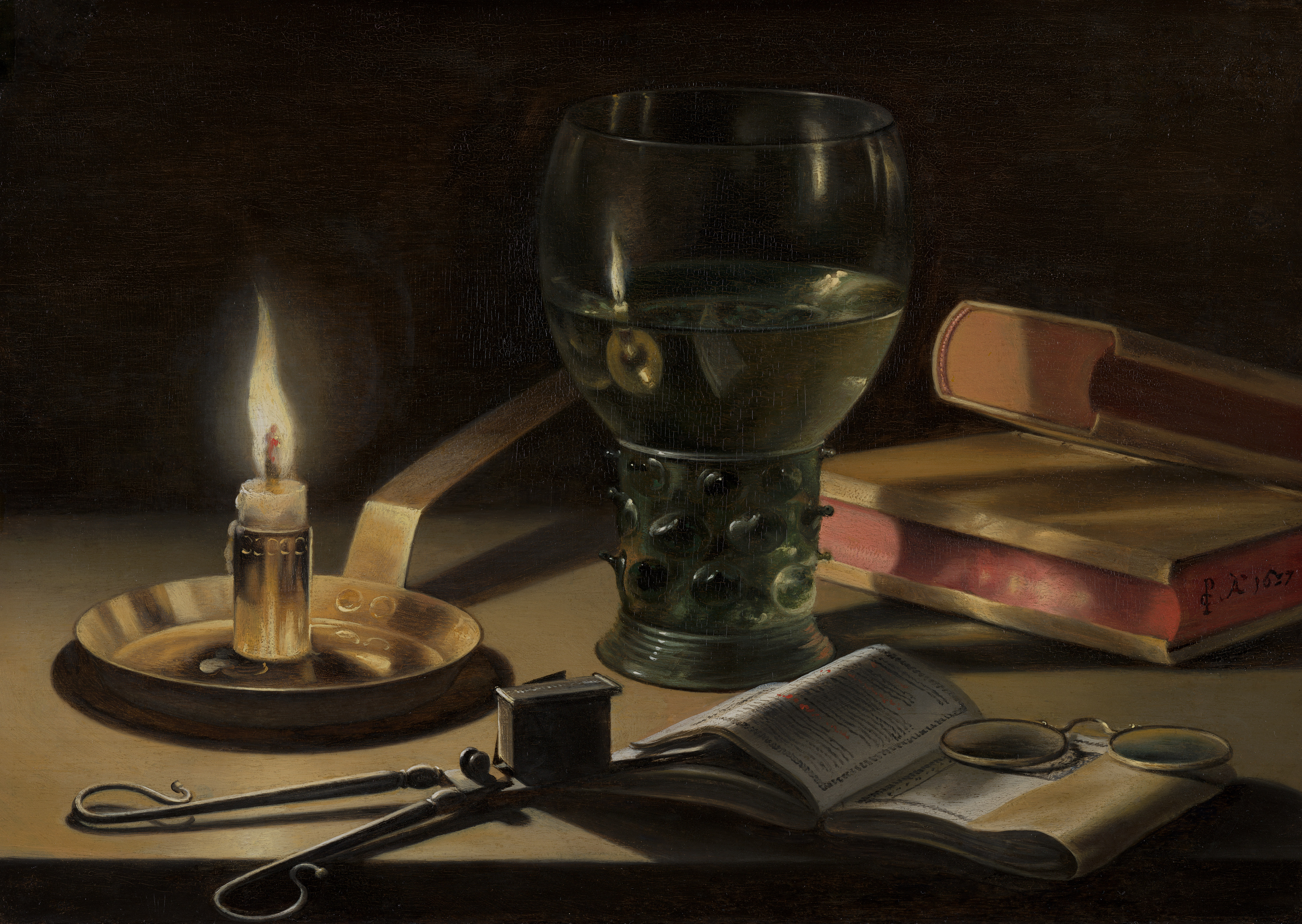
Figure 8: Claesz 1627 Reference Image (Still Life with Lighted Candle)