Spiral Peel
So I’ve recently been playing around with Houdini quite a bit, initially as the base for implementing my Master’s thesis work, but now moreso for the general fun of making random small visual effects. For now, I’m going to attempt to document how I make various effects, largely as a reference for myself. I highly suggest against reading this as a tutorial for Houdini as there is quite a lot of resources available online for that (the fine duo at Entagma in particular are a key resource for myself). In any case, I’m very much a beginner and the way I do some effects are likely not ideal.
As is likely apparent, the general aesthetics of the final picture draws heavily from vaporwave, simultaneously rather obscure music (I’m not convinced anyone unironically listens to it on a regular basis) as well as a widely-known part of internet culture. None of that particularly matters here other than the whole classical sculpture aesthetic mixed with the teal and pink colour scheme.
The final composition is actually inspired by one particular drawing a saw online but now can no longer find. Perhaps I should actually use the pin feature on Pinterest for once.
How-To
So the general effect we’re trying to achieve here is this spiral orange-peel of some given geometry. You’d expect this would take at most maybe five nodes (and perhaps it could actually be that easy, I certainly wouldn’t know) – Houdini certainly has the shatter and Boolean tools to separate a piece of geometry into separate pieces. Simon Holmedal actually has such an effect here that I do want to recreate eventually.
The difference for a spiral cut is that we’re not actually separating pieces – we still end up with a single piece, it just happens to be extremely long. No new topology is being made, but the cuts also end up separating quite a lot of nearby points.
The main idea is quite simple, though. All we’re really going to do is to take a spiral tape and cylindrically project it onto our surface. This certainly isn’t the most accurate way of performing this since we could have geometry that overhangs from the cylindrical perspective (as we’ll see later), but for nearly cylindrically-shaped models (which really are the only ones that you can get good-looking spiral cuts for) it’s good enough while also being fast. There are ways to actually perform a spiral cut in Houdini by intersecting geometry and splitting the primitives, but they’re considerably slower.
Setup Mesh
So as usual, the first thing to do is to setup the actual mesh we want to cut. I got the mesh of Alexander as Helios from thingiverse. This isn’t actually the exact bust that shows up on the cover art for Floral Shoppe (the preeminent vaporwave album) – note the hair – but it’s close. As well, I think a lot of these models on thingiverse are setup for 3D printing with gcode, so the units are actually massive and I end up needing to scale it down by several orders of magnitude (and also polyreduce it to ~10% of its initial detail).
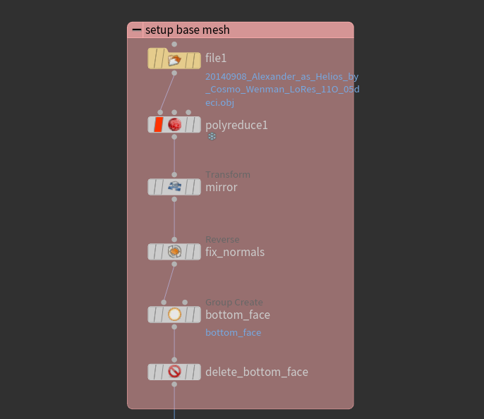
Figure 1: Setup initial mesh.
There isn’t anything of note here, other than perhaps one must always remember to fix the normals when using a -1 scale transform to mirror since that operation ends up placing the normals interior. As well, I want to make sure to have an open mesh so I cut out the bottom face of the model.
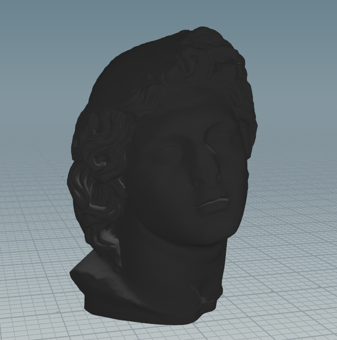
Figure 2: Starting mesh.
Make Spiral
To setup the spiral, all we need to do is to define a line with a lot of subdivisions, then use a point wrangle to place the points using trig functions modulated by the y-position. Again, nothing all too interesting. Then, to make the spiral faces, we just extrude each point downward to make rectangular faces. This is also where we determine the resolution of the grid that we project onto our mesh. I think it’s sensible to choose a grid resolution that’s about the same as the mesh resolution.
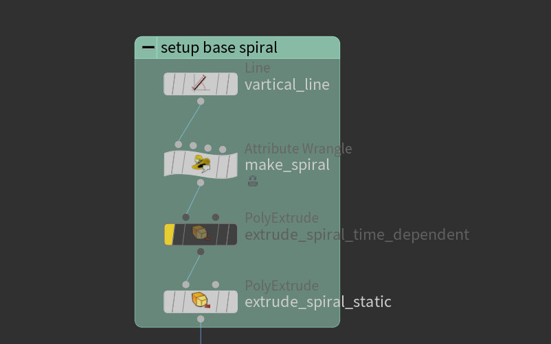
Figure 3: Setup spiral.
A key detail to note here is that we want inward-facing normals, since we will be using them to project the spiral towards the geometry. Additionally, we make an integer point attribute colnum to keep track of how far up the point is along the spiral. This will be useful later when trying to separate the spirals in the y-axis. The particular piece of vex I use to do all this is as follows:
\\ make spiral
@P.x = 3*sin(ch("nspiral")*2*@P.y*3.1415/(5));
@P.z = 3*cos(ch("nspiral")*2*@P.y*3.1415/(5));
\\ setup inwards normals
@N.x = -@P.x;
@N.z = -@P.z;
@N = normalize(@N);
\\ set how far up this point is on the spiral
i@colnum = @ptnum;
At this point, you should end up with a spiral that looks like this:
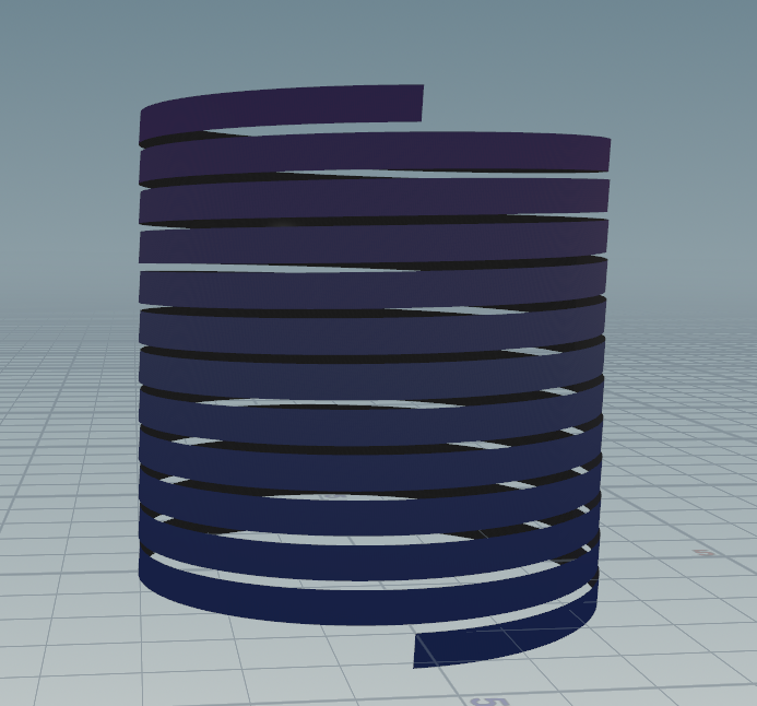
Figure 4: The spiral tape coloured according to colnum.
I should also mention it is important to make sure to make the spiral wide enough to contain the whole geometry in all axes.
Cylindrical Projection
Now, we’re ready to do the cylindrical projection. To do this, we use the ray SOP, which projects points along their normals. We select our spiral tape as the input geometry to deform, and our target mesh as the collision geometry.
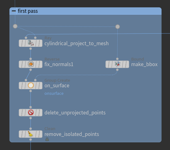
Figure 5: Cylindrical projection nodes.
If you made the spiral tape large enough, you will end up with extra unprojected pieces at the start and end. To delete these, we simply create a bounding box on our target mesh, then say any points outside the bounding box are unprojected points and thus are safe to delete.
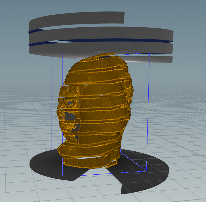
Figure 6: Cylindrical projection, with points to keep highlighted in orange.
At this point, our geometry is looking basically done. However, you might notice that some parts of our target mesh wasn’t properly resolved. These are left by overhangs in the cylindrical projection, and require another projection pass to properly handle.
Refining the Projection
Getting better definition in the overhanging parts is a somewhat more involved than everything done up to this point. My solution here isn’t actually perfectly robust - there may be very deep overhands (ie along multiple axes) that don’t get resolved, as well as the colnum attribute defined earlier not transferring to a few points. Nonetheless, this is the best I have at the moment so we charge on.
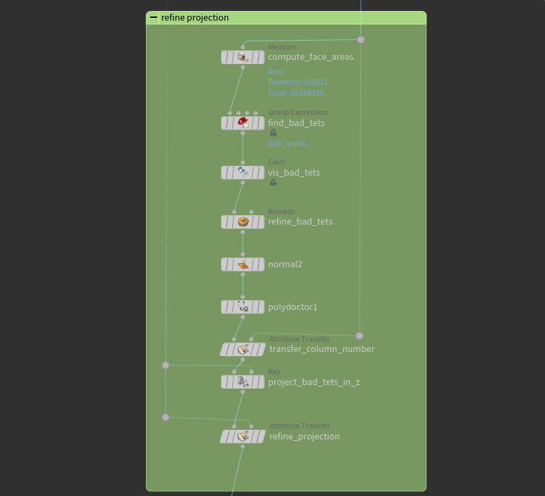
Figure 7: Refining the mesh.
The first thing we need to do is to figure out which parts are actually the overhangs. I tried looking for Houdini nodes that could detect bad quads, but polydoctor ends up being fairly slow. The solution that ends up working quite well is just simply noticing that most elements projected on an ideal surface end up with similar areas. When they get projected onto an overhang, however, they get stretched over the overhang like cling wrap – so all we need to do is to check which quads are larger than the others, and set a threshold on how badly stretched quads are allowed to be. Houdini has the handy measure SOP that can compute face areas, then we just create a primitive group with all the stretched quads.
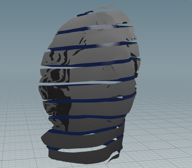
Figure 8: Detected stretched quads coloured in black.
Now, since these faces are stretched, we need to actually make good-sized faces before projecting. We just use the remesh node with a target uniform edge lengths, then fix normals and use polydoctor to clean up the mesh a bit. With good geometry, we can now just project along the axis we consider best captures the missing geometry – along the negative z-axis in this case. Note, though, that when projecting, we need to offset our ray a bit in the opposite direction to make sure that points already on the target geometry don’t shoot past it and get sent to the other side, making bad artifacting. We then use an attribute transfer SOP to smooth out the projection as well as making sure the colnum attribute gets inherited correctly.
At this point, we’re done! We can use the colnum attribute as an easy way of differentially animating along the length of the tape. Here, I used it to simulate a gravity effect a bit by pulling the bottom parts of the tape down according to a quadratic offset.
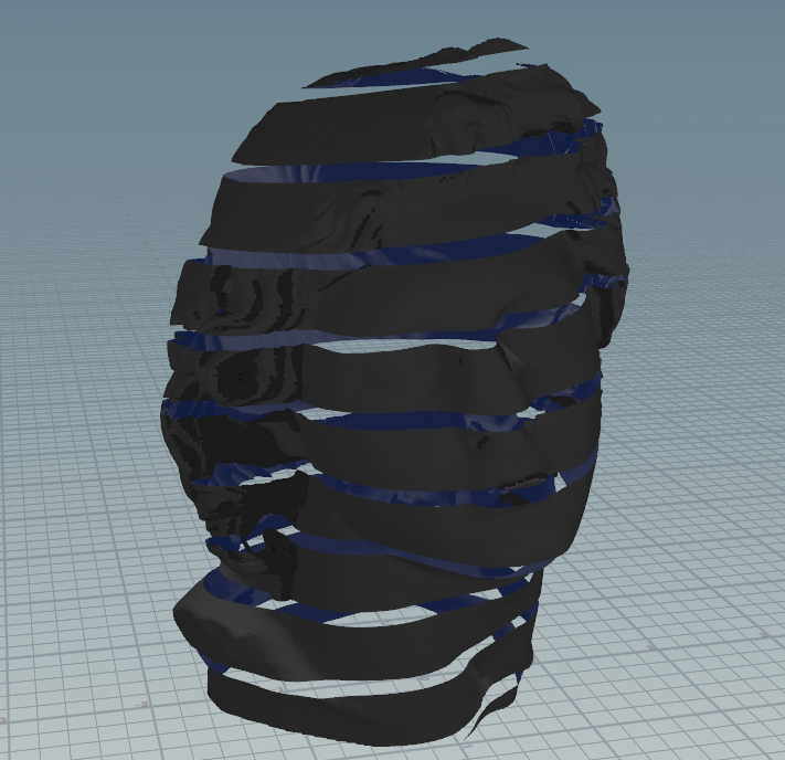
Figure 9: Fixed overhangs.